MEP Expand
MEP Expand Description
This tool is designed to speed up the creation of MEP (Mechanical, Electrical, Plumbing) routing in your project. It's worth noting that the current options for this tool are specialized for conduit. With MEP Expand, you can simplify the process of routing conduit in your project, making it more efficient and less time-consuming. This tool provides you with various routing options, including Kick 90, Stub 90, Offset, 4 Point Saddle, and 3 Point Saddle, allowing you to choose the most suitable method for your project needs.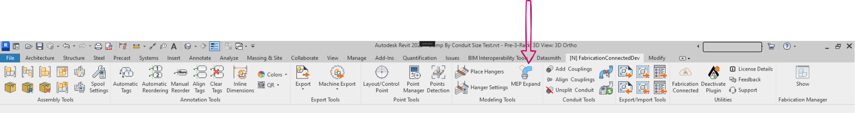
Kick 90 Option
"Kick 90" is a feature commonly used in the context of ductwork or piping systems within Revit. It represents a 90-degree elbow designed to connect two components that are positioned at a 90-degree angle to each other and are at different heights or elevations. This functionality serves the purpose of altering the direction of the duct or pipe while accommodating variations in elevation. "Kick 90" is particularly valuable when you encounter obstacles in your design or when your system layout necessitates simultaneous changes in both direction and elevation. In essence, it connects two parts that meet at a 90-degree angle and are not at the same height.
Step-by-Step Guide
- Access MEP Expand: Click on the "MEP Expand" icon in your toolbar.
- MEP Expand Window: Once you click the icon, the MEP Expand window will open, revealing the following options.
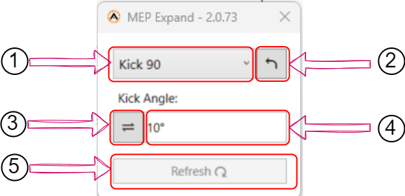
- MEP Expand Dropdown: From this MEP Expand Dropdown" dropdown Select "Kick 90" choose the "Kick 90" option. This sets the tool to create a 90-degree bend.
- Undo Action Button: You can use the "Undo Action" button to reverse any connections that have been made between parts, whether by you or anyone else.
- Reverse Direction: If you wish to change the start/end direction of your MEP routing, click on the "Reverse Direction" icon.
- Specify Kick Angle: You can define the angle of the kick (bend) you want to create. You can choose from the dropdown options or enter a customized angle as needed.
- Refresh: Click the "Refresh" button to update your part with the latest settings.
- Select Parts for "Kick 90" Application: After specifying your "Kick 90" setting, go to the project viewer and select the parts to which you want to apply these changes. This allows you to target and modify specific components with the chosen "Kick 90" settings.
Stub 90 Option
"Stub 90" simplifies the process of generating 90-degree extensions for conduits in your project. This tool allows you to effortlessly create precise conduit extensions at a fixed length, ensuring accurate routing and efficient design. Whether you're working on electrical, plumbing, or HVAC systems, "Stub 90" simplifies the process, saving you time and enhancing your overall productivity in Revit. It is particularly useful when you need to connect parts that meet at a 90-degree angle.
Step-by-Step Guide
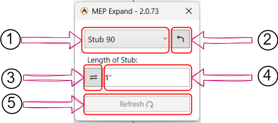
- Open MEP Expand: Open the "MEP Expand" tool. This will open a new pop-up window where you can control your settings.
- MEP Expand Dropdown: Within the pop-up, use the Dropdown (1) to select from various MEP options. Choose "Stub 90" for this particular task.
- Undo Action Button: You can use the "Undo Action" button (2) to undo any connections that have been made between parts, whether by you or anyone else.
- Reverse Direction: If you wish to change the start/end direction of your MEP routing, click on the "Reverse Direction" icon (3).
- Specify Stub Length: In the "Length of Stub" field, insert the desired length of the stub you want in your project. This determines the size of the 90-degree extension.
- Refresh Button: Click the "Refresh" button to update your part with the latest settings.
- Now, go to the project viewer and select the parts to which you want to apply the "Stub 90" changes. This allows you to target specific components for the 90-degree extensions.
Offset
"Offset" is a option that allows you to modify the position or elevation of components within your project. It is particularly valuable for accommodating architectural and structural constraints. This tool is used to connect two parts that have an offset between them, and you have the flexibility to specify the offset angle as needed. It's a crucial tool for ensuring precise alignment and routing in your design.
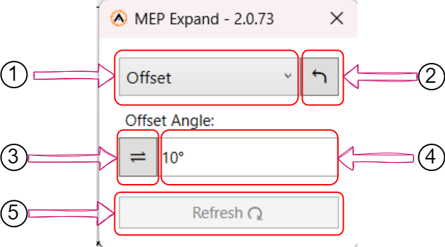
- Open MEP Expand: Open the "MEP Expand" tool. This will open a new pop-up window where you can control your settings.
- MEP Expand Dropdown: Within the pop-up, use the Dropdown to select from various MEP options. Choose "Offset" for this particular task.
- Undo Action Button: You can use the "Undo Action" button to undo any connections that have been made between parts, whether by you or anyone else.
- Reverse Direction: If you wish to change the start/end direction of your MEP routing, click on the "Reverse Direction" icon.
- Specify Offset Angle: In the "Length of Stub" field, insert the desired angle of the of you want in your project.
- Refresh Button: Click the "Refresh" button to update your part with the latest settings.
- Now, go to the project viewer and select the parts to which you want to apply the "Offset" changes.
4 Point Saddle option
The "4 Point Saddle" option in MEP Expand simplifies the creation of complex bends for conduit and piping. It's especially useful for routing around obstacles, maintaining alignment, and enhancing design efficiency in electrical and plumbing projects.
Step-by-Step-Guide
- Open MEP Expand: Open the "MEP Expand" tool. This will open a new pop-up window where you can control your settings.
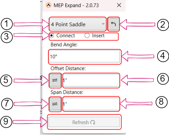
- MEP Expand Dropdown: Within the pop-up, choose "4 Point Saddle" from the Dropdown menu.
- Undo Action Button: Utilize the "Undo Action" button to undo/reverse any connections made between parts.
- Choose Connection Type: Specify whether you want to insert into an already connected part or between two separate parts.
- Specify Bend Angle: Define the desired bend angle in degrees for the 4 Point Saddle configuration.
- Reverse Offset Distance: If you need to change the direction of your offset distance, use the "Reverse Offset Distance" option.
- Insert Offset Distance: Enter the offset distance value as needed.
- Reverse Span Direction: If you wish to change the direction of your span distance, you can use the "Reverse Span Direction" option.
- Insert Span Distance: Type the span distance value you require.
- Refresh Button: Click the "Refresh" button to update your part with the latest settings.
- Select Parts for "4 Point Saddle": Finally, navigate to the project viewer and select the parts you want to apply the "4 Point Saddle" changes to.
Note: When you select a custom angle, you will notice a ![]() icon at the end of the input box. This icon allows you to delete your custom angle and revert to selecting from the available angle choices in the dropdown menu.
icon at the end of the input box. This icon allows you to delete your custom angle and revert to selecting from the available angle choices in the dropdown menu.
3 Point Saddle
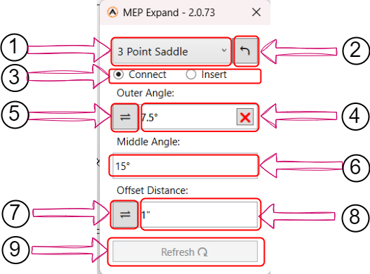
- Open MEP Expand: Open the "MEP Expand" tool. This will open a new pop-up window where you can control your settings.
- MEP Expand Dropdown: Within the pop-up, choose "3 Point Saddle" from the Dropdown menu.
- Undo Action Button: Utilize the "Undo Action" button to reverse or undo any connections that have been made between parts.
- Choose Connection Type: Specify whether you want to insert into an already connected part or between two separate parts.
- Specify Outer Angle: Input the preferred outer angle as the outer angle defines the orientation of the saddle connection. .
- Reverse Outer Angle: Click on the "Reverse Outer Angle" icon if you wish to reverse the outer angle direction. Reversing the outer angle may be necessary to align the saddle connection correctly, especially when dealing with complex part configurations
- Input Middle Angle: Type in the value for the middle angle. The middle angle determines the positioning of the saddle's central point. Accurate input ensures the connection aligns precisely with your project's requirements.
- Reverse Offset Distance: Click on this icon to reverse the offset distance. Reversing the offset distance is important for adjusting the position of the saddle connection and its offset from the connected parts.
- Input Offset Distance: Enter the offset distance value as needed, Setting the correct offset distance ensures that the saddle connection fits precisely within your project's layout
- Refresh Button: Click the "Refresh" button to update your part with the latest settings.
- Select Parts for "3 Point Saddle": Finally, navigate to the project viewer and select the parts you want to apply the "3 Point Saddle" changes to.
Note: When you select a custom angle, you will notice a ![]() icon at the end of the input box. This icon allows you to delete your custom angle and revert to selecting from the available angle choices in the dropdown menu.
icon at the end of the input box. This icon allows you to delete your custom angle and revert to selecting from the available angle choices in the dropdown menu.
Created with the Personal Edition of HelpNDoc: Streamline your documentation process with HelpNDoc's WinHelp HLP to CHM conversion feature